
 Berita
I. Ciri-ciri Asas Gelombang Radio
Anggaran masa membaca: 15 minit
1.1 Definisi Gelombang Radio
Gelombang radio berfungsi sebagai pembawa isyarat dan tenaga, yang dihasilkan oleh gandingan bersama medan elektrik dan magnet yang berayun, mematuhi hukum gandingan berselang-seli "elektrik menghasilkan kemagnetan dan kemagnetan menghasilkan elektrik". Semasa perambatan, medan elektrik dan magnet sentiasa berserenjang antara satu sama lain dan kedua-duanya berserenjang dengan arah perambatan gelombang, menjadikannya **Gelombang Elektromagnet Melintang (gelombang TEM)**.

Penjanaannya berasal daripada litar berayun frekuensi tinggi: apabila arus dalam litar berubah dengan pantas dari semasa ke semasa, medan elektromagnet berselang-seli teruja di ruang sekeliling. Sebaik sahaja medan elektromagnet ini terpisah daripada sumber gelombang, ia merambat melalui ruang dalam bentuk gelombang radio, tanpa bergantung pada sebarang medium—ia juga boleh memancar dalam vakum.
1.2 Hubungan antara Panjang Gelombang, Frekuensi dan Kelajuan Perambatan
Formula teras yang mengawal hubungan antara panjang gelombang (λ), frekuensi (f) gelombang radio dan kelajuan perambatannya (kelajuan cahaya \( C \) dalam vakum, lebih kurang \( 3×10^8 \, \text{m/s} \)) ialah:
\[ \lambda = \frac{C}{f} \]
**Kesimpulan Utama**: Dalam medium yang sama, frekuensi dan panjang gelombang adalah berkadar songsang—semakin tinggi frekuensi, semakin pendek panjang gelombang. Hubungan ini secara langsung menentukan dimensi reka bentuk antena: contohnya, panjang gelombang antena
WiFi 2.4GHz
isyarat adalah lebih kurang 12.5 cm, sepadan dengan panjang antena dipol separuh gelombang kira-kira 6.25 cm; untuk a
700MHz
Isyarat komunikasi frekuensi rendah, panjang gelombangnya adalah lebih kurang 42.8 cm, memerlukan panjang dipol separuh gelombang sebanyak 21.4 cm. Di samping itu, prestasi elektrik antena (seperti kecekapan sinaran, gandaan dan impedans) secara langsung berkaitan dengan **panjang elektrik** (nisbah panjang fizikal kepada panjang gelombang). Dalam kejuruteraan praktikal, panjang elektrik yang diperlukan mesti ditukar kepada panjang fizikal tertentu untuk memastikan antena beroperasi dengan baik.
1.3 Pengkutuban Gelombang Radio
Polarisasi merujuk kepada hukum variasi arah medan elektrik apabila gelombang radio merambat, ditentukan oleh trajektori gerakan ruang vektor medan elektrik, membentuk spektrum lengkap: **Polarisasi Bulatan ← Polarisasi Elips → Polarisasi Linear**. Ciri-ciri teras dan senario aplikasi ketiga-tiganya adalah seperti berikut:
- **Polarisasi Linear**: Arah medan elektrik kekal tetap, bentuk polarisasi yang paling biasa digunakan. Gelombang dengan medan elektrik yang berserenjang dengan tanah ialah **gelombang terkutub menegak**, yang mempunyai rintangan yang kuat terhadap gangguan pantulan tanah dan sesuai untuk komunikasi mudah alih terestrial (cth., stesen pangkalan 2G/3G tradisional); gelombang dengan medan elektrik selari dengan tanah ialah **gelombang terkutub mendatar**, yang biasa digunakan dalam penghantaran radio dan televisyen, komunikasi geganti gelombang mikro dan senario lain.
- **Polarisasi Bulatan**: Trajektori vektor medan elektrik adalah bulat, dibahagikan kepada **polarisasi bulatan kiri** dan **polarisasi bulatan kanan**, yang saling eksklusif (antena kiri hanya boleh menerima gelombang terkutub bulatan kiri, dan sebaliknya). Kelebihan utamanya ialah rintangan yang kuat terhadap gangguan berbilang laluan dan kilasan polarisasi, menjadikannya digunakan secara meluas dalam komunikasi satelit (cth.,
Beidou
,
GPS
satelit), alat kawalan jauh kenderaan udara tanpa pemandu (UAV) dan senario lain.
- **Polarisasi Elips**: Trajektori vektor medan elektrik adalah elips, bentuk umum polarisasi—polarisasi bulat berlaku apabila paksi major dan minor elips adalah sama, dan polarisasi linear apabila paksi minor menghampiri sifar. Dalam persekitaran komunikasi sebenar, disebabkan oleh pantulan berbilang laluan, oklusi halangan dan faktor lain, gelombang terkutub linear atau bulat tulen sering ditukar menjadi gelombang terkutub elips.
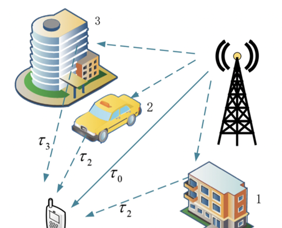
1.4 Penyebaran Berbilang Laluan
Apabila gelombang radio merambat, selain gelombang langsung, ia mengalami pantulan, pembelauan dan penghantaran apabila menghadapi halangan seperti bukit, hutan dan bangunan, mengakibatkan terminal penerima menerima gelombang radio berbilang laluan secara serentak—satu fenomena yang dikenali sebagai **penyebaran berbilang laluan**. Impak utamanya termasuk: (1) Merumitkan taburan kekuatan isyarat, menyebabkan "pudar bayang" dan "pudar pantas" dan membawa kepada turun naik yang teruk dalam kekuatan isyarat di hujung penerima; (2) Mengubah arah polarisasi gelombang radio, mengakibatkan ketidakpadanan polarisasi dan mengurangkan kekuatan isyarat yang diterima; (3) Menjana penyebaran kelewatan (perbezaan masa antara isyarat yang tiba melalui laluan yang berbeza), menyebabkan gangguan antara simbol; (4) Menyebabkan superposisi isyarat tempatan (peningkatan) atau pembatalan (kelemahan, bergantung pada hubungan antara perbezaan laluan dan panjang gelombang). Contohnya, di kawasan bandar yang padat, pantulan bangunan menghasilkan sebilangan besar isyarat berbilang laluan, yang membawa kepada turun naik yang kerap dalam kekuatan isyarat yang diterima oleh telefon bimbit.
Penyelesaian teras untuk isu ini ialah **teknologi penerimaan kepelbagaian**, yang menerima dan menggabungkan isyarat berbilang laluan untuk mengurangkan gangguan. Ia dibahagikan kepada dua kategori:
1. **Kepelbagaian Ruang**: Menggunakan berbilang antena berkutub tunggal dengan susun atur ruang yang munasabah (jarak lebih daripada 10 kali panjang gelombang) untuk menerima isyarat melalui laluan yang berbeza. Sesuai untuk senario dengan keperluan pengkutuban yang rendah.
2. **Kepelbagaian Polarisasi**: Memanfaatkan ciri-ciri ortogon antena dwi-terkutub untuk menerima dua isyarat terkutub menegak secara serentak (cth., +45°/-45°). Disebabkan oleh korelasi isyarat yang rendah, output gabungan meningkatkan kebolehpercayaan penerimaan dengan ketara, menjadikannya penyelesaian arus perdana untuk arus
5G
stesen pangkalan.